
A Rotary Actuator Symbol is more than a small mark on an engineering drawing. It represents a device that converts fluid, pneumatic, or electrical energy into controlled rotary motion. In a schematic, that compact graphic may identify turning direction, shaft movement, operating medium, and control conditions. A clear symbol helps engineers read the system before touching the equipment.
This matters in modern automation. The International Federation of Robotics reported 541,302 industrial robots installed worldwide in 2023 in its World Robotics 2024 report. Many robotic cells depend on rotary actuators for gripping, indexing, positioning, and valve control. Their drawings must communicate quickly across design, manufacturing, maintenance, and procurement teams. ISO 1219-1 and ISO 1219-2 provide established graphical rules for fluid-power systems. IEC 60617 also supports consistent electrotechnical symbols and database-based documentation.
However, a Rotary Actuator Symbol is not always universal. Its meaning depends on the drawing standard, actuator technology, and additional control symbols nearby. A vane actuator may appear differently from a rack-and-pinion actuator. Electrical rotary actuators may require motor, feedback, and limit-switch indicators. Small details matter. A missing arrow can obscure rotation direction. An unclear port label can delay commissioning.
This guide explains how to identify the symbol, interpret its functional elements, and compare common schematic conventions. It also considers practical documentation problems. Even experienced engineers can misread simplified graphics. That is worth remembering. Reliable interpretation requires checking the legend, applicable standard, datasheet, and actual actuator configuration before making technical decisions.
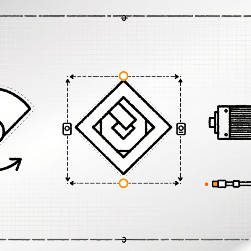
What Is a Rotary Actuator Symbol?
Definition and Purpose of a Rotary Actuator Symbol
A rotary actuator symbol is a simplified graphic used in pneumatic, hydraulic, or electrical schematics. It represents a device that converts fluid pressure or electrical energy into rotary motion. The symbol helps engineers identify movement without drawing the actuator’s physical housing, shaft, or internal parts.
In a pneumatic diagram, the symbol often shows a circular body with an arrow, shaft, or curved motion mark. These details indicate rotation, direction, or adjustable travel. A double-headed arrow may suggest reversible movement. A single arrow can indicate one-way rotation, although conventions differ between standards. The drawing alone is not enough. Always check the diagram legend.
The purpose is practical. Technicians can trace motion from a valve to an actuator and then to a machine component. This makes troubleshooting faster during commissioning or maintenance. For example, a curved arrow beside a shaft may show that a gripper turns 90 degrees. A small spring mark may indicate a return mechanism. Symbols also reduce clutter on complex equipment drawings.
In real schematic reviews, unclear symbols can cause costly assumptions. I have found that even experienced readers may interpret a rotation arrow differently. That is worth questioning. Engineers should confirm the applicable drafting standard, actuator type, rotation angle, and control method before installation. A correct symbol supports reliable communication, but it cannot replace detailed specifications.
A rotary actuator symbol is a compact visual language used on pneumatic, hydraulic, or control diagrams. It shows how pressurized fluid creates controlled rotation. In practice, technicians read it before touching a valve or tracing a hose. The central circle usually represents the actuator body. A curved arrow inside indicates rotational movement. Clockwise and counterclockwise arrows can show one-way or reversible operation. The arrow alone does not always specify speed. That detail is often missing.
Small connection lines, or ports, identify where fluid enters and leaves. Two ports commonly suggest bidirectional rotation. One port may appear with a spring or return mechanism, depending on the design. A shaft symbol extends from the circle and marks the output point. Nearby angle markings, such as 90° or 180°, define the working rotation. A flow arrow can clarify the active direction, but it should not be confused with the shaft arrow. I have seen drawings where poor spacing makes these arrows look identical. That is a real interpretation risk.
Reliable interpretation requires checking the legend, symbol standard, and actuator specification together. Some diagrams simplify the housing and omit internal vanes, racks, or pistons. Others add damping, feedback, or fail-position marks. A crossed line may indicate a disabled path, not a damaged component. Never infer torque from the symbol alone. Confirm pressure, load, rotation angle, and fail-safe behavior in the technical data. Symbols guide decisions, but context gives them meaning.
What Is a Rotary Actuator Symbol?
How Rotary Actuator Symbols Represent Motion and Control
A rotary actuator symbol is a compact drawing used in pneumatic, hydraulic, or automated control diagrams. It shows how pressurized energy creates shaft rotation. The symbol often includes a circular body with an arrow. The arrow indicates the direction of rotation. A curved arrow can show reversible movement. Simple, but not always enough.
Port markings reveal how fluid or air enters the actuator. Two ports usually represent clockwise and counterclockwise control. When pressure reaches one port, the shaft turns one way. Pressure at the opposite port reverses the movement. A single port may indicate one powered direction. A spring symbol often shows the return action after pressure disappears.
Control symbols add more information. Lines connected to valves can show electrical, pneumatic, or manual commands. A small solenoid mark may identify an electrically controlled valve. A hand lever or pilot line suggests another control method. Flow arrows help technicians trace the operating sequence.
During commissioning, I compare the drawing with the installed shaft position. Diagrams can appear correct while the actuator turns opposite to expectations. That mistake is easy to miss. Labels, port numbers, and rotation arrows should be checked together. Symbol standards improve communication, yet local drafting habits still create confusion. I have found that a quick physical test often exposes unclear assumptions before they affect machine timing.
| Symbol | Symbol Element | What It Represents | Motion or Function | Typical Control Information |
|---|---|---|---|---|
| ↻ | Rotary motion arrow | A curved arrow placed inside or beside the actuator symbol indicates rotational output. | The shaft turns around a fixed axis rather than moving linearly. | The arrow direction may indicate clockwise or counterclockwise rotation when the viewing direction is defined. |
| ↺↻ | Two opposing arrows | Opposing curved arrows represent reversible rotation. | The actuator can rotate in both directions, commonly called bidirectional or double-acting rotation. | Direction is selected by changing the pressurized or energized control path. |
| ○↻ | Circular actuator body | A circle or circular body identifies a rotary actuator rather than a standard linear cylinder. | Fluid pressure, electrical energy, or another input produces torque at an output shaft. | The symbol may be paired with hydraulic, pneumatic, or electrical connection details. |
| ↻ 90° | Angular travel marking | An angle value specifies the permitted or intended shaft rotation. | Common quarter-turn applications use 90° travel; other designs may use 180°, 270°, or continuous rotation. | The angle should be checked against the actuator specification and the driven mechanism. |
| ↻ + ⏹ | Mechanical stop | A stop marking indicates a physical limit on shaft movement. | The shaft stops at a defined angular position instead of rotating freely through the full range. | Stops may establish end positions, but they do not necessarily indicate position feedback. |
| P A/B | Working ports | Port labels identify the connections used to drive the actuator. | Alternating pressure or flow between two working ports can produce opposite shaft directions. | P commonly denotes supply pressure, while A and B commonly identify actuator working connections. |
| P → A | Flow or signal path | An arrow in a connected line shows the intended direction of fluid flow or control transmission. | Flow into one control path can initiate rotation in the associated direction. | Actual operation depends on the valve configuration, pressure, flow rate, and load conditions. |
| ↻⌁ | Electrical drive indication | A motor or electrical-drive reference identifies an actuator powered by electrical energy. | Electrical input is converted into rotary torque and shaft movement. | The drawing may additionally show power, control, feedback, brake, or limit-switch connections. |
| ↻ ⇆ | Feedback indication | A feedback connection indicates that shaft position, speed, or rotation may be monitored. | Measured output can be used to verify or regulate actuator movement. | Typical feedback devices include limit switches, potentiometric sensors, encoders, or resolvers. |
| ↻ |S | Spring-return indication | A spring marking indicates stored mechanical energy that biases the actuator toward a defined position. | When the driving force is removed, the shaft returns toward the spring-selected position. | The return direction and fail position must be confirmed from the complete schematic and actuator data. |
| T | Torque reference | Torque identifies the turning force available at the output shaft. | Higher required load torque generally requires a suitable safety margin and correctly sized actuator. | Torque can vary with pressure, voltage, speed, duty cycle, temperature, and mechanical efficiency. |
| n | Speed reference | Speed indicates how quickly the shaft rotates, commonly expressed in revolutions per minute. | The actuator may provide fixed, adjustable, or controlled rotational speed. | Hydraulic and pneumatic speed is affected by flow; electric speed is affected by motor and controller characteristics. |
Note: Rotary actuator symbols can vary between hydraulic, pneumatic, electrical, and industrial control drawings. Always read the complete schematic legend, connection labels, arrow direction, travel limits, and control specifications together.
A rotary actuator symbol represents a device that converts fluid, electrical, or mechanical energy into rotation. Its appearance changes across engineering diagram standards. In fluid-power drawings, a circle usually indicates rotary motion, while arrows show direction. A curved arrow may identify limited-angle movement, such as 90 or 180 degrees. A motor symbol can suggest continuous rotation instead.
The difference is small. The meaning is not.
ISO 1219-1 provides symbols for fluid-power systems, including actuator functions and port connections. IEC 60617’s public catalogue contains more than 1,900 graphical symbol entries, showing how wide diagram conventions can become. Electrical schematics may use a motor circle with terminals, while process diagrams often add control signals, valve positions, or fail-safe directions. ISA-style drawings can place the actuator above a valve body, but other systems place it beside the valve. Always check the project legend.
In commissioning work, I have seen a familiar symbol misread as continuous rotation. The actuator only moved a quarter turn. That mistake delayed testing. Engineers should verify the angle, energy source, rotation direction, and spring-return condition. Line weight and arrow placement also matter. A clean drawing can still be incomplete. The uncomfortable part. Standards guide interpretation, but local conventions sometimes win.
A rotary actuator symbol shows how fluid or electrical energy creates angular motion. In pneumatic and hydraulic drawings, ISO 1219-1 defines the main graphical language for fluid power circuits. Look for a circular or semicircular actuator shape, connected ports, and an arrow showing rotation. The arrow direction matters. A double-headed arrow often indicates reversible rotation. A spring symbol may show return action, while a small control symbol can indicate speed adjustment or cushioning.
Read the symbol with its nearby labels. Port markings identify supply, exhaust, or return paths. A valve symbol beside the actuator explains how motion starts and stops. If the drawing includes a feedback line, the actuator may report position to a controller. This detail is easy to miss. During commissioning, technicians often compare the schematic with hose routing and shaft movement. That practical check can reveal reversed ports or an incorrect rotation direction.
The symbol does not show every performance limit. Torque, rotation angle, pressure, and response time usually appear in a specification table. The International Federation of Robotics reported 541,302 industrial robot installations worldwide in 2023, showing how common motion systems have become. More automation also means more complex drawings. I still pause when a symbol looks familiar but lacks a clear actuator type. ISO 1219-1:2012 should guide interpretation, yet project conventions can differ. Verify the legend before connecting power or pressure.
To learn more about any of the products and services provided by Abbott Ball Company, Inc., simply complete the form below.