Top 10 Types of Mechanical Shaft Seals for Buyers
Choosing a Mechanical Shaft Seal is not just a matter of matching a part number. The right design depends on the fluid, pressure, temperature, shaft speed, and equipment layout. A seal handling clean water may not perform well with abrasive slurry or a volatile process fluid. Details matter.
Buyers will encounter several designs, including pusher, non-pusher, cartridge, balanced, unbalanced, and split seals. Each addresses different operating conditions and maintenance needs. A cartridge seal, for example, arrives preassembled, which can reduce installation errors. A split seal may suit equipment that cannot be easily dismantled. But no type is universally best.
This guide introduces ten common mechanical shaft seal types and explains the practical differences buyers should consider. It looks at how each design works, where it is typically used, and what questions to ask suppliers. Check material compatibility, operating limits, expected maintenance access, and the manufacturer’s installation guidance before making a decision. These details can prevent premature leakage and avoidable downtime.
Specifications do not tell the whole story. Actual service conditions may differ from a plant’s original assumptions, and wear patterns can reveal overlooked problems. It depends. Treat the comparisons as a starting point, then verify the choice against your equipment data and operating experience.
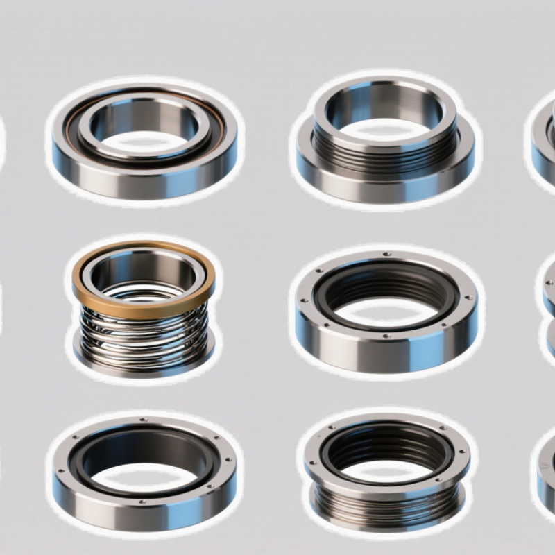
Mechanical Shaft Seals: How Mating Faces Control Leakage
Across the ten common types of mechanical shaft seals, mating faces are a key control on leakage. One face rotates with the shaft; the other stays fixed. Their finely lapped surfaces form a narrow sealing gap, not a perfectly dry, frictionless barrier. A thin liquid film usually lubricates the faces and carries away heat. Small details matter.
If the faces run too far apart, fluid can escape. If they press together too hard, friction may cause heat, wear, or cracking. Proper face loading, shaft alignment, and surface finish help keep the gap stable. For example, vibration or shaft runout can disturb contact even when a seal looks suitable on paper. The fluid itself matters, too: abrasive particles can score faces, while poor lubrication during startup can damage them quickly.
When comparing single, double, balanced, or other seal arrangements, buyers should ask how the face pair suits the pressure, temperature, fluid, and operating cycle. Harder face materials may resist wear, but they are not automatically the best choice for every service. A catalog comparison can miss this. Real operating data is more useful than assumptions, and even a careful selection may need adjustment after installation. Check the specified flush or barrier-fluid conditions, alignment limits, and maintenance records before deciding.
Seal Design Basics: Pusher, Non-Pusher, Balanced, and Unbalanced
Choosing a mechanical shaft seal starts with the machine’s pressure, temperature, fluid, and movement. A pusher seal uses a sliding secondary seal that moves along the shaft or sleeve as the faces wear. That motion helps maintain contact. It can also bind if deposits build up or the shaft surface is damaged. A non-pusher design, often using a flexible bellows, accommodates wear without that sliding secondary seal. Its flexibility is useful, but the available movement and material limits matter. Bellows are not a universal fix.
Balanced and unbalanced describe how hydraulic pressure loads the seal faces. In an unbalanced design, pressure creates greater force between the faces. This can suit lower-pressure service, but extra contact force may mean more heat and wear. A balanced seal reduces that hydraulic closing force, making it a common choice for higher pressures or heat-sensitive duties. “Balanced” does not mean trouble-free. Face materials, shaft runout, dry running, and installation still affect performance. Before choosing, check the equipment’s operating range and seal limits, and look closely at alignment during installation; even a sound design can disappoint when the faces are set unevenly.
Ten Mechanical Shaft Seal Types by Construction and Arrangement
Top 10 Types of Mechanical Shaft Seals for Buyers
Mechanical shaft seals differ by construction, face loading, and installation arrangement. A pusher seal uses a sliding secondary seal to maintain contact as faces wear. A non-pusher design, often using metal bellows, avoids that sliding motion. It can suit demanding temperatures, but material choice matters.
Balanced seals reduce hydraulic force on the sealing faces, helping manage higher pressure. Unbalanced seals are simpler, though pressure limits require careful checking. A single seal has one sealing interface. Double seals use two, often with a barrier fluid between them; tandem seals place two seals in series, usually with a buffer fluid. The arrangements are not interchangeable. Process conditions decide.
Cartridge seals arrive assembled, which can reduce installation errors and setup time. Split seals separate into sections, allowing fitting around a shaft without major equipment disassembly. Gas-lubricated seals use grooves to create a thin gas film between faces, limiting contact and friction.
Labels can overlap: a cartridge seal may also be balanced or double. Check shaft runout, temperature, pressure, fluid properties, and available space before choosing. Small installation details matter. Even experienced teams sometimes miss them.
API 682 and ISO 21049: 3 Seal Categories and 3 Arrangements
API 682, also published as ISO 21049, groups mechanical seals into three categories and three arrangements. These are selection frameworks, not ten interchangeable seal designs. Category 1 covers less demanding service; Categories 2 and 3 address progressively more rigorous design and qualification needs. Check the actual pressure, temperature, speed, and fluid conditions before choosing. The category label alone cannot settle the choice.
Arrangement 1 uses a single seal, often with a flush or quench plan suited to the process. Arrangement 2 uses dual seals with an unpressurized buffer system; Arrangement 3 uses dual seals with a pressurized barrier system. In the field, the distinction matters: barrier pressure, reservoir level, and piping details affect whether the setup protects the process as intended. Small details count.
The U.S. Department of Energy’s Improving Pumping System Performance sourcebook reports that pumping systems can consume 25–50% of a facility’s industrial energy use. That figure is not a seal-performance claim, but it shows why leakage, maintenance access, and downtime deserve attention during pump selection. A useful review pairs the API 682 or ISO 21049 category and arrangement with the plant’s operating data. I would still question any selection based only on a catalog duty point.
Buyer Selection Criteria: Pressure, Temperature, Speed, Fluid, and Materials
Mechanical shaft seals should be chosen against actual operating conditions, not a catalog description alone. Pressure affects face loading and leakage risk, while temperature can change elastomer flexibility and fluid viscosity. A balanced seal may suit higher pressure, but the manufacturer’s stated limits still need checking. Small details matter.
Speed creates heat at the seal faces. A seal that performs well on a slow mixer may struggle on a fast pump, especially during dry running or frequent starts. Review the shaft diameter, rotational speed, and cooling conditions together. Check the fluid. Abrasive particles may call for harder face materials, such as silicon carbide, while cleaner fluids may work with carbon against a ceramic or silicon carbide face. Compatibility charts help, but real mixtures and additives can complicate the choice.
Material selection includes more than the seal faces. Elastomers must tolerate the process fluid and temperature range; common options include EPDM, FKM, and PTFE-based components, each with limits. Metal bellows designs can avoid some elastomer concerns, while cartridge seals may simplify installation and reduce setup errors. Split seals can help where equipment cannot be easily dismantled. A neat specification sheet can still mislead if it omits pressure spikes, flushing, or occasional dry starts. Confirm those details with the equipment supplier, and leave a margin rather than selecting right at a stated limit.