
MON - FRI 8AM - 5PM

How to Wire a Winch Rocker Switch?

A Winch Rocker Switch looks simple on a dashboard: a compact toggle, a few terminals, and two short wire runs. Yet those connections control a powerful recovery system. A loose ground can leave the winch unresponsive; incorrect wiring can damage the switch or create a hazard. Small details matter.

This guide explains how to identify the switch terminals, follow the winch manufacturer’s wiring diagram, and connect control wires without confusing them with the heavy battery cables. You’ll see why wire gauge, secure terminals, and a properly rated circuit protection device deserve attention. Before touching the wiring, disconnect power and check the winch and switch manuals. Keep the work area dry. Label each wire. Then verify the connections before restoring power. It is tempting to rely on wire colors alone. Don’t. Colors vary between products.

A credible expert quotation should be verified against its original source. No source article or attributable expert statement was provided, so this introduction does not invent a name or quote. Insert a confirmed quotation here: “[Verified expert’s exact words],” says [Expert Name], [relevant qualifications or organization]. That extra check may feel fussy. It protects readers from false authority. Wiring also rewards a second look: a switch can click normally while a terminal remains loose. The following steps focus on careful identification and manufacturer-approved connections, not guesswork.
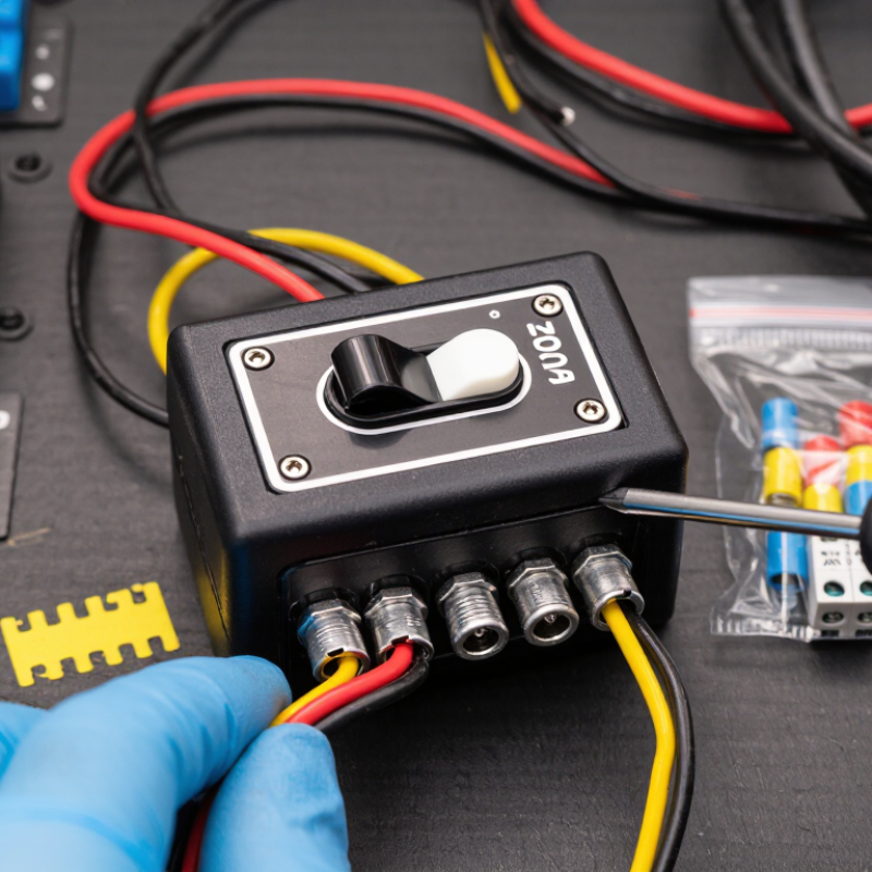
How to Wire a Winch Rocker Switch?

Winch Rocker Switch Types and Operating Principles

A winch rocker switch usually controls a solenoid, not the winch motor’s heavy current. Two common types are momentary and maintained switches. A momentary switch powers a direction only while you press it, then springs back to neutral. A maintained switch stays in position until moved again. For most winch controls, momentary operation helps prevent accidental, sustained movement.

Many rocker switches use a double-pole, double-throw arrangement to reverse the control signals for “in” and “out.” Other models send separate signals to a solenoid pack. Check the switch diagram and terminal markings before connecting wires; similar-looking switches may have different internal layouts. Labels can mislead. Disconnect the battery before work, use wire suited to the control circuit, and protect that circuit with the specified fuse. Never route motor-current cables through a switch unless it is explicitly rated for that load.

Tips: With the battery disconnected, identify power, ground, and direction terminals from the wiring diagram. Secure connections against vibration, then test each direction briefly in a clear area. If the winch moves opposite to the rocker label, stop and recheck the control wiring. It is easy to assume the colors match; they may not.

How a Winch Rocker Switch Works

This chart shows the idealized polarity commands for a reversing winch motor on a nominal 12 V system. A momentary rocker switch typically selects one direction, neutral, or the opposite direction; the control circuit reverses motor polarity to change direction. Actual wiring and measured voltage vary by winch and system.

Note: “Forward” and “reverse” are generic direction labels. Check the winch wiring diagram to identify which rocker position pulls in or pays out the cable.

Tools, Materials, and Safety Precautions

Before wiring a winch rocker switch, identify whether it controls a solenoid or carries motor current; these circuits need different switch ratings. Check the winch wiring diagram, switch specifications, and cable-size chart. Gather insulated hand tools, a digital multimeter, a proper wire crimper, heat-shrink terminals, and abrasion-resistant loom. Match every connector to the cable gauge. Keep parts clean and dry.

Disconnect the battery’s negative terminal before work. BLS’s 2022 Census of Fatal Occupational Injuries recorded 145 fatal work injuries involving exposure to electricity; that figure is not winch-specific, but it shows why electrical hazards deserve care. Fit the specified fuse or circuit protection, and place it as directed by the wiring instructions. Route wires away from hot exhaust, sharp edges, and moving winch parts. Secure them with clamps, not tight bends. Small details matter. I would still recheck polarity and continuity before reconnecting power; a neat-looking crimp can be loose inside. Test the switch with the winch unloaded, stand clear of the cable path, and stop if a wire warms, sparks, or smells burnt.

Identify the Switch Terminals and Winch Wiring

Identify the switch terminals from its wiring diagram, not from their position alone. Disconnect the battery before testing. On a common six-terminal, double-pole, double-throw rocker, the center pair often connects to the motor leads; crossed outer connections reverse polarity. But layouts vary. Do not guess. Use a multimeter’s continuity mode to confirm which terminals connect in each switch position, then label them before wiring.

Check whether the rocker controls a solenoid pack or carries motor current. Many winch switches operate only the solenoid; routing motor current through an underrated switch can overheat contacts and insulation. Match the switch rating to its actual load, and keep the heavy battery and motor cables sized for current and cable length. SAE J1127 specifies performance requirements for low-voltage battery cable, but it does not replace the winch maker’s wiring diagram. A tidy terminal layout can still conceal a crossed connection.

For voltage-drop context, ABYC E-11 guidance uses a 3% limit for critical circuits. Treat that as a useful design reference, not a substitute for the winch’s specified cable size. Secure terminals against vibration, cover exposed positive connections, and test briefly with the winch unloaded. Stop if the switch, cable, or connections warm noticeably. Recheck the diagram; assumptions are easy to miss.

Connect the Switch to the Winch and Power Source

A winch rocker switch should usually command the contactor, not carry the winch motor’s full current. Check the winch wiring diagram and switch rating before connecting anything. Disconnect the battery first. Use the specified cable gauge, and measure the complete cable route, including the return path. A cable that looks thick can still lose voltage over a long run.

Connect the switch’s control wires to the contactor terminals shown in the diagram; polarity and terminal labels matter. Route the contactor’s heavy cables between the battery, winch, and ground as specified, with the required fuse or circuit breaker close to the battery.

ABYC’s E-11 electrical standard gives a 3% voltage-drop limit for critical circuits and 10% for other loads. A winch can draw heavy current, so use its cable chart rather than treating that 10% figure as a target.

Small details matter. Secure cables away from sharp edges and hot parts, then check that no terminal can rotate or touch the frame.

I would recheck the switch diagram here; confusing a control terminal with a motor terminal is an easy mistake.

Reconnect power only after checking every connection, then test the rocker briefly with the area clear. Use a multimeter to confirm the switch changes the contactor control circuit as intended.

Test the Wiring and Troubleshoot Common Issues

After wiring a winch rocker switch, test it with the vehicle secured, transmission in park, and winch area clear. With power disconnected, check continuity through the switch in each position. Reconnect power and test both directions briefly. Test under load. A click without drum movement often points to a weak battery, poor ground, loose terminal, or faulty solenoid—not necessarily the switch. Use a multimeter to compare battery voltage with voltage at the winch terminals while the switch is held. Keep hands and clothing clear of the cable.

A voltage reading can look fine with no load, then sag when the motor draws current. Measure voltage drop across the positive and ground paths separately, and inspect warm or discolored connections. The ABYC E-11 marine electrical standard sets voltage-drop limits of 3% for critical circuits and 10% for other circuits. Treat these figures as reference points, not universal winch specifications; follow the winch maker’s stated limits when available. I admit this check is easy to rush. If the switch gets hot, the fuse opens repeatedly, or the motor runs in only one direction, stop testing and trace the circuit before replacing parts.

Request a Quote

To learn more about any of the products and services provided by Abbott Ball Company, Inc., simply complete the form below.